> For the complete documentation index, see [llms.txt](https://evoffer.gitbook.io/evoffer-installation-guide/llms.txt). Markdown versions of documentation pages are available by appending `.md` to page URLs; this page is available as [Markdown](https://evoffer.gitbook.io/evoffer-installation-guide/model-s/alpharex-luxx-series-tail-light.md).
# Alpharex LUXX-Series Tail Light
This is the installation guide for Tesla Model S LUXX-Series Tail Light from Alpharex (Sold by EVOffer).
{% embed url="" %}
{% hint style="info" %}
*The demo car is a Tesla Model S 2017 with Premium Package (Power Liftgate), Ultra High-field Sound Option, EU standard Motorized Charge Port. It may be a little bit different from your car depending your car option and model year.*
{% endhint %}
## Packing List
1. Left Inner Tail Light x 1
2. Left Outer Tail Light x 1
3. Right Inner Tail Light x 1
4. Right Outer Tail Light x 1
5. Gloss Black Center Applique x 1
6. Light Extension Wire x 2
7. Rear Fog & Reverse Light Wire Harness x 1 (For non-North America Version)
8. Brake Wire Harness x 1 (For North America Version)
## Tools
1. 8mm Hex Socket
2. T-20 Screwdriver
3. T-30 Screwdriver
4. Small Flat Head Screwdriver
5. Fishing Tape
## Installation
### Step 1 - Removing trunk lid panels
First, remove the cup holders on the trunk lid panel. Disconnect the trunk closing button connector if you have power liftgate option.
Remove the 3 trim pieces as shown in the following photo.
Unscrew the 2 T-20 screws on both sides of the trunk lid cover.
Gently take off the trunk lid cover. There are 1-4 connectors for speakers and LED light, depending your model year and audio options. Disconnect all of them in order to take out the cover.
### Step 2 - Remove and replace the applique
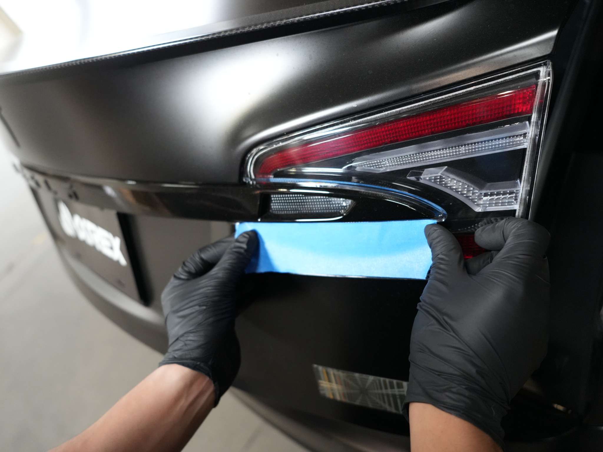
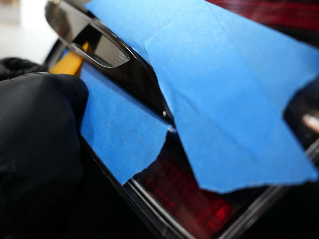
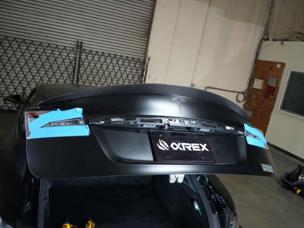
Use some tapes to protect the inner tail lights.
Use a plier, pry tool or fishing line to detach the tape behind the applique.
Take out the center trim piece.
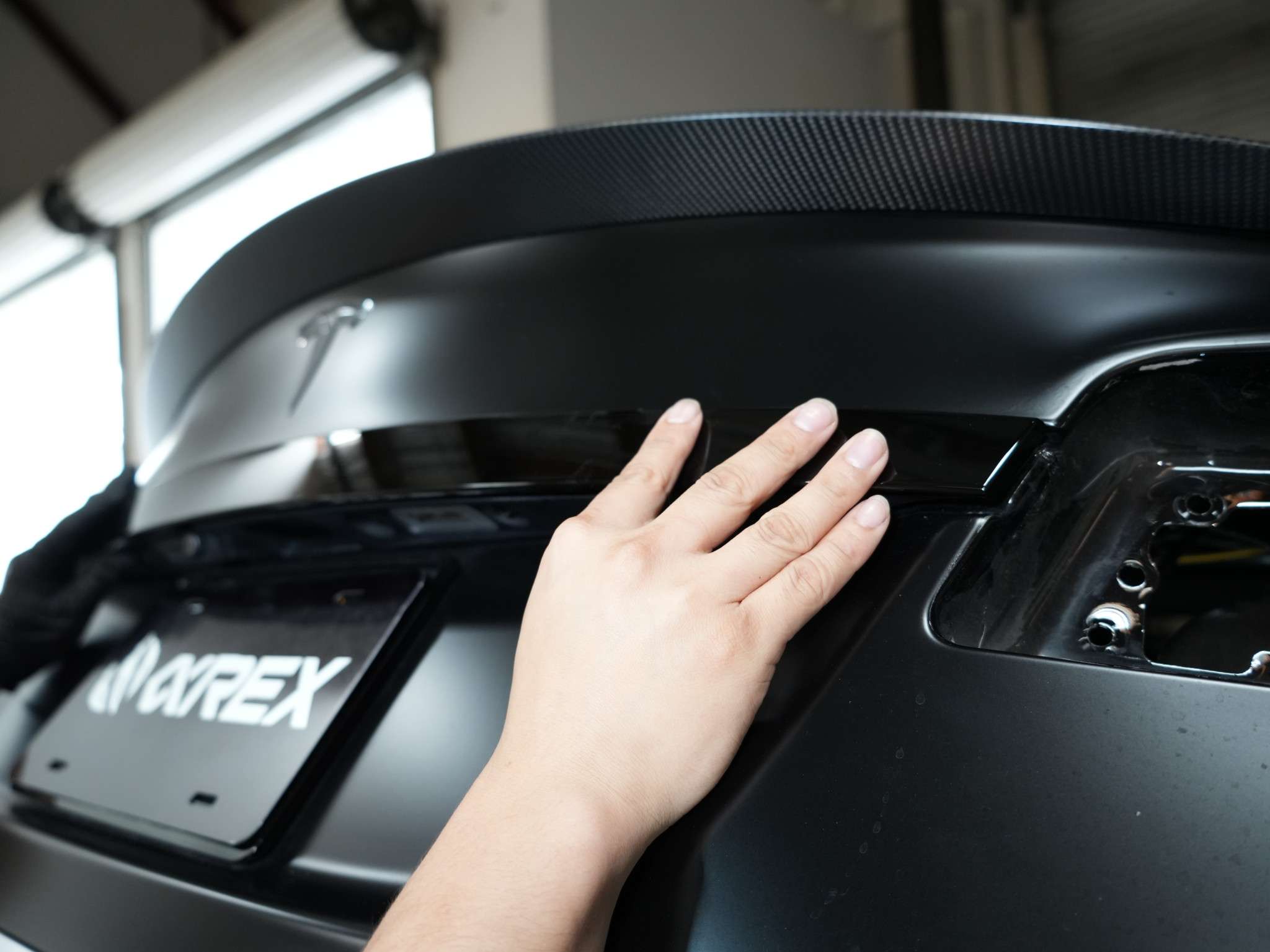
Install the provided gloss black center trim piece.
### Step 3 - Remove and replace inner tail lights
Disconnect the tail light connector.
Unscrew the 4 8mm nuts to remove the original tail lights.
Install the new inner lights. Align the light and tighted with the 4 8mm nuts.
### Step 4a - Install brake light wire harness (For North America version)
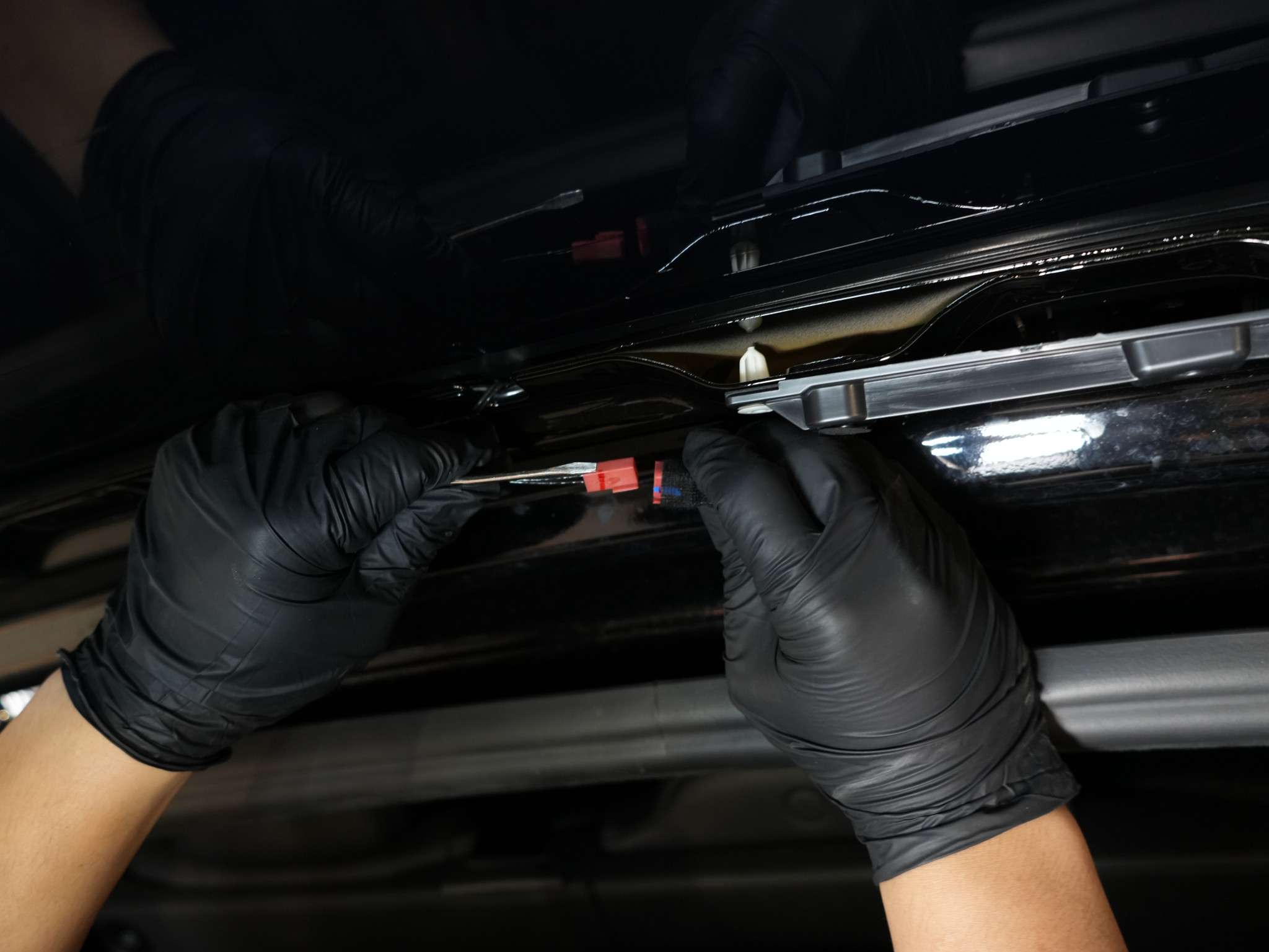
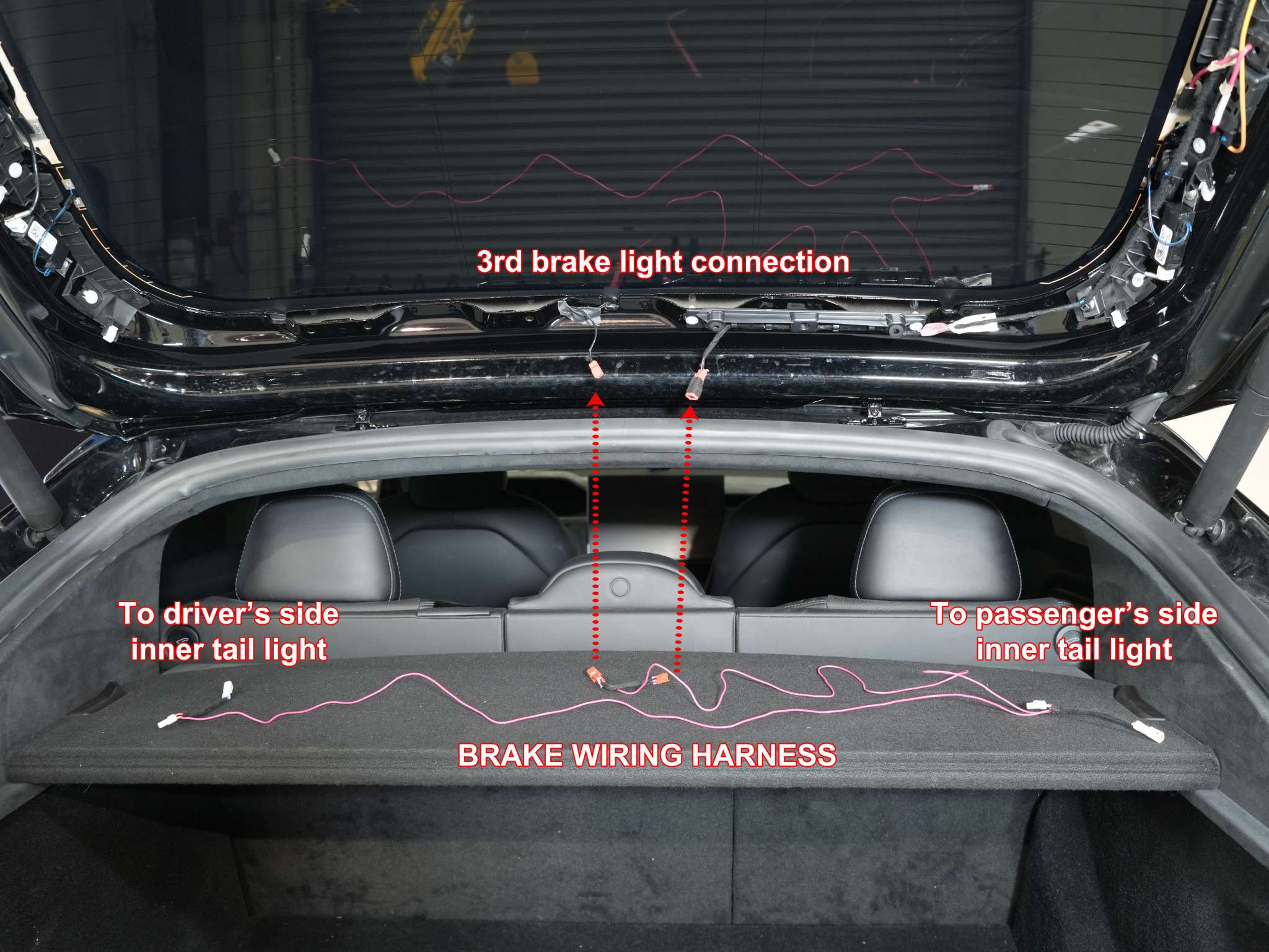
Disconnect the vehicle’s third brake light connection.
Connect the connectors to the vehicle’s third brake light connection, then route the wire harness to each side of the inner tail light assembly location.
### Step 4b - Install rear fog & reverse light wire harness (For non-North America version)
The tail light is applicable to both LHD and RHD cars. You should find two set of connectors with blue-white wires but in different orders.
Here is an illustration for the wire connection.
**For LHD cars (Reverse Light on the Right Side):**
* Connect L1 to L3
* Connect R2 to R3
* Connect L2 to R1 (with the extra cable)
**For RHD cars (Reverse Light on the Left Side):**
* Connect L2 to L3
* Connect R1 to R3
* Connect L1 to R2 (with the extra cable)
### Step 5 - Remove and replace the outer tail lights
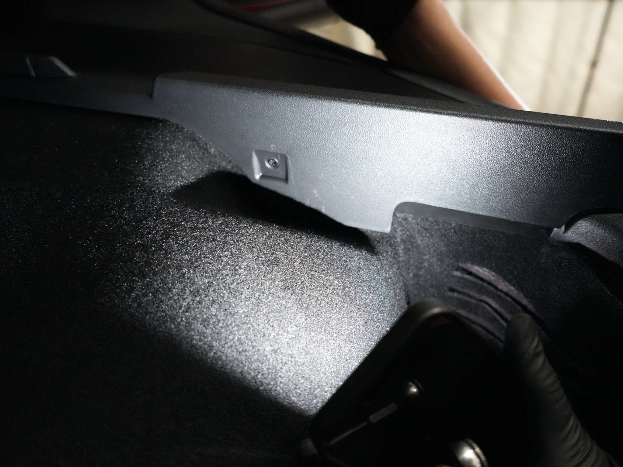
Remove the plastic trim covers from the trunk cargo space.
Remove the screws on both sides of the trunk cargo plastic cover panels.
Use some masking tapes to protect the paints before replacing the tail lights.
Remove the cover for the charge port. Make sure the magnet is still attached to the cover. Otherwise the charge port will not work after reinstalling everything.
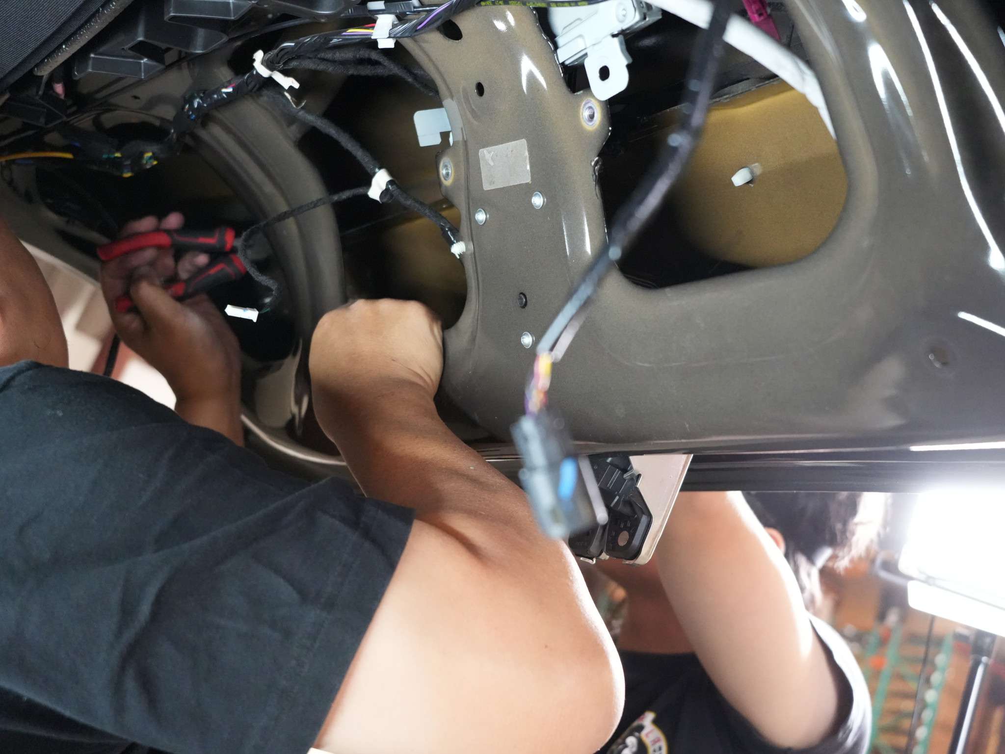
Unscrew the 3 T-30 screws. Just leave them hanging there. Disconnect the charge port light connector (if any).
Unscrew the 4 T-30 screws that hold the charge port bracket.
The charge port can be taken out now. Jiggle and take out the center part first and then the bracket.
If you have a motorized charge port, you also need to disconnect the charge port door connector.
Now remove the 4 8mm nuts that hold the tail lights.
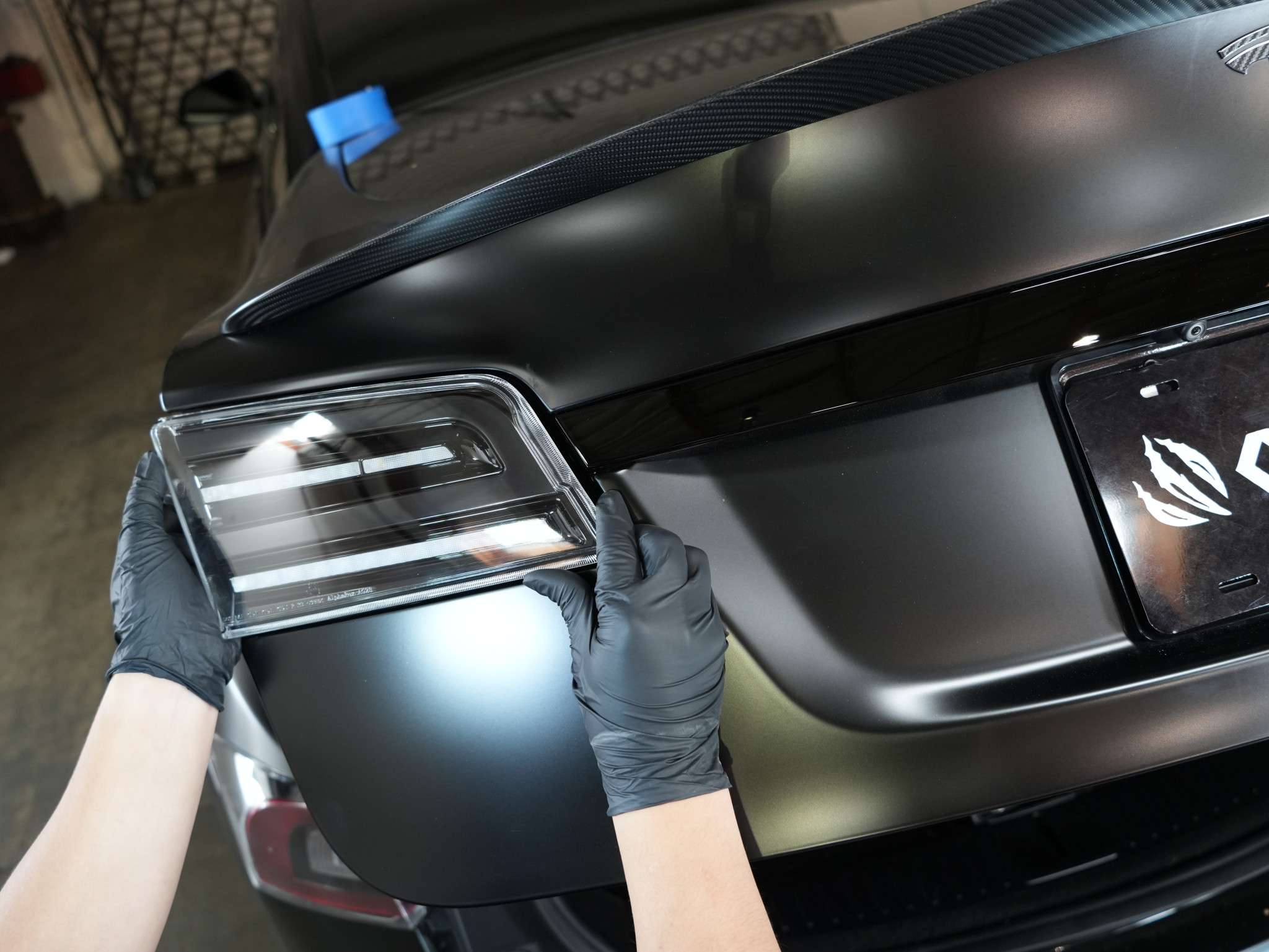
Slide out the tail light gently.
Remove the 3 T-20 screws that hold the panel or charge port door on the old tail lights and transfer them to the new tail lights.
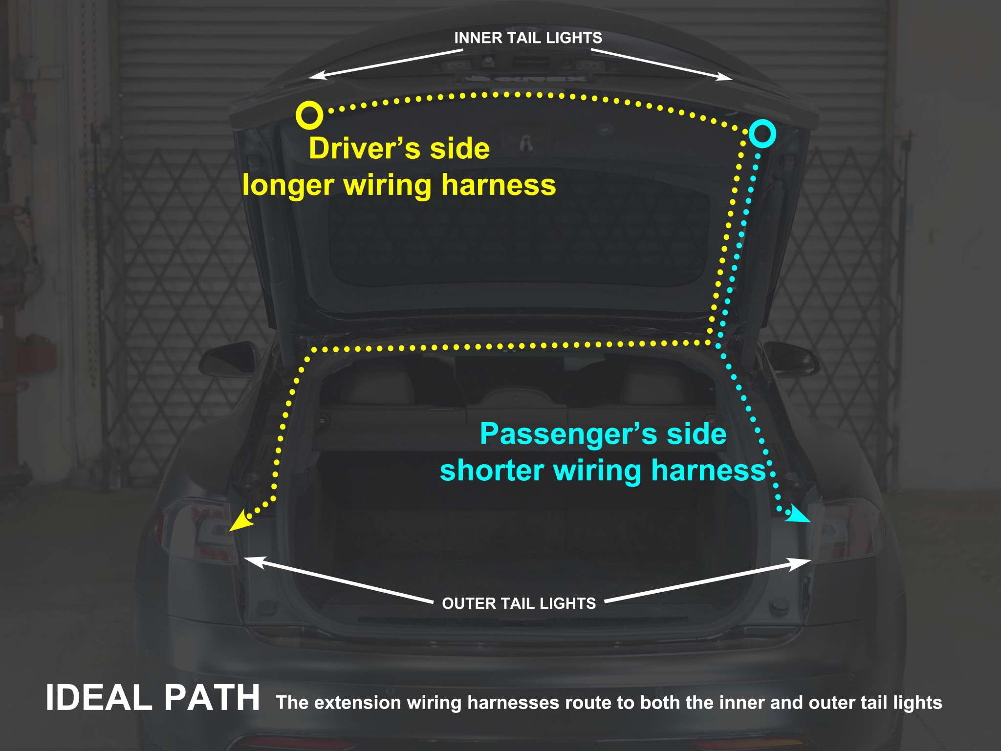
### Step 6 - Run the light extension wire harness
Run the wire from outer left to inner left light; from outer right to inner right light.
Here is the wiring diagram for the 2 wires.
### Step 7 - Set the animation
There are 2 green wires on each lights. They are used to turn on or off the animation on each light.
With the green wires connected:
* Tail light boot animation is set to OFF
* Sequential turn signal is set to OFF
With the green wires disconnected:
* Tail light boot animation is set to ON
* Sequential turn signal is set to ON
### Step 8 - Finishing Up
Tidy up all wires and trim pieces, install them in reverse procedures. Now test all the lighting effects and see if they are working properly.